| Lesson 3 | What is a relational database? |
| Objective | Define a relational database. |
What is a Relational Database?
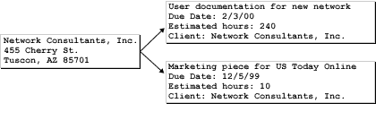
The example of a database we have discussed so far, a phone book, is really just a single table with a single set of fields. Most of the data in the real word is not this simple. Some data, in fact most data, works better in a database with multiple tables. This is where a relational database comes in. A relational database has multiple tables so that you can store and analyze multiple lists of related data. This is necessary because although data is related, there is not always a one-to-one relationship between different categories (fields) of data, making it difficult to figure out how to design the table. For instance, to keep track of clients you can create a table to hold client names and contact information. However, you would also like to keep track of the projects you do. Each project is for a client, but you may do more than one project for a client. This graphic shows how you might store this data on index cards with one card for each client, and one card for each project.

-
Main Rectangle (Network Consultants, Inc.)
- Located at the top-left corner.
- Represents a client entity, providing identifying information like name and address.
- Example Data: "Network Consultants, Inc.", "455 Cherry St., Tucson, AZ 85701."
-
Two Smaller Rectangles (Tasks/Projects)
- Positioned to the right of the main rectangle.
- Represent task/project entities associated with the client.
- Example Data for Each:
- Task 1: "User documentation for new network" with a due date, estimated hours, and client name.
- Task 2: "Marketing piece for US Today Online" with a due date, estimated hours, and client name.
-
Arrows
- Point from the main rectangle (client) to each of the smaller rectangles (tasks/projects).
- Indicates a one-to-many relationship, where one client can have multiple associated tasks or projects.
Relationship:
-
Entity Relationship:
- The primary entity is "Client," and the related entities are "Tasks/Projects."
- One client (
Network Consultants, Inc.) can be linked to multiple tasks/projects.
This structure mirrors a common database schema where a client table has a foreign key in the tasks/projects table, enabling the tasks to reference their associated client.
Simple Schema to represent the Relationship
Here's a simple schema to represent the relationship between the "Client" (left rectangle) and the "Tasks/Projects" (two right rectangles):
Schema Representation
Entity Relationship
Example SQL Code to Create Schema
This schema models the relationship shown in the image, with `Clients` as the parent entity and `Tasks` as the child entity.
Schema Representation
-
Client Table
- Table Name:
Clients - Fields:
ClientID(Primary Key): Unique identifier for the client.ClientName: Name of the client (e.g., "Network Consultants, Inc.").Address: Client address (e.g., "455 Cherry St., Tucson, AZ 85701").
- Table Name:
-
Tasks/Projects Table
- Table Name:
Tasks - Fields:
TaskID(Primary Key): Unique identifier for the task/project.TaskName: Description of the task/project (e.g., "User documentation for new network").DueDate: Due date of the task (e.g., "2/3/00").EstimatedHours: Estimated hours required for the task (e.g., "240").ClientID(Foreign Key): References theClientIDin theClientstable to establish the relationship.
- Table Name:
Entity Relationship
-
One-to-Many:
- One client in the
Clientstable can have many associated tasks in theTaskstable. - The relationship is achieved through the
ClientIDfield, which acts as a foreign key in theTaskstable.
- One client in the
Example SQL Code to Create Schema
CREATE TABLE Clients (
    ClientID INT PRIMARY KEY,
    ClientName VARCHAR(255) NOT NULL,
    Address VARCHAR(255)
);

CREATE TABLE Tasks (
    TaskID INT PRIMARY KEY,
    TaskName VARCHAR(255) NOT NULL,
    DueDate DATE,
    EstimatedHours INT,
    ClientID INT,
    FOREIGN KEY (ClientID) REFERENCES Clients(ClientID)
);
This schema models the relationship shown in the image, with `Clients` as the parent entity and `Tasks` as the child entity.
Detailed Analysis based on the Previous Schema

Here's the detailed analysis based on the previous schema:
Components:
-
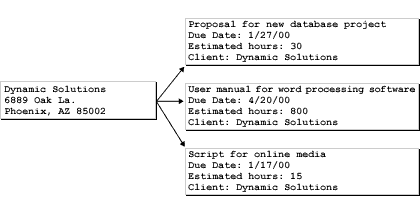
Main Rectangle (Dynamic Solutions)
- Located on the left.
- Represents the client entity, providing identifying information such as:
- Name: Dynamic Solutions
- Address: 6889 Oak La., Phoenix, AZ 85002
-
Three Smaller Rectangles (Tasks/Projects)
- Positioned to the right of the main rectangle.
- Represent tasks/projects associated with the client.
- Details for Each Task/Project:
- Task 1: "Proposal for new database project"
- Due Date: 1/27/00
- Estimated Hours: 30
- Client: Dynamic Solutions
- Task 2: "User manual for word processing software"
- Due Date: 4/20/00
- Estimated Hours: 800
- Client: Dynamic Solutions
- Task 3: "Script for online media"
- Due Date: 1/17/00
- Estimated Hours: 15
- Client: Dynamic Solutions
- Task 1: "Proposal for new database project"
-
Arrows
- Point from the main rectangle (client) to each of the smaller rectangles (tasks/projects).
- Indicates a one-to-many relationship, where one client can be linked to multiple tasks/projects.
Entity Relationship:
-
Parent Entity: Client (Dynamic Solutions)
- One client can have multiple associated tasks/projects.
-
Child Entities: Tasks/Projects
- Each task is uniquely associated with a single client through a foreign key relationship.
Updated Schema for This Image:
-
Client Table
- Table Name:
Clients - Fields:
ClientID(Primary Key)ClientName: "Dynamic Solutions"Address: "6889 Oak La., Phoenix, AZ 85002"
- Table Name:
-
Tasks/Projects Table
- Table Name:
Tasks - Fields:
TaskID(Primary Key)TaskName: e.g., "Proposal for new database project"DueDate: e.g., 1/27/00EstimatedHours: e.g., 30ClientID(Foreign Key, referencesClients.ClientID)
- Table Name:
Example SQL Code for This Scenario:
INSERT INTO Clients (ClientID, ClientName, Address)
VALUES (2, 'Dynamic Solutions', '6889 Oak La., Phoenix, AZ 85002');

INSERT INTO Tasks (TaskID, TaskName, DueDate, EstimatedHours, ClientID)
VALUES
(4, 'Proposal for new database project', '2000-01-27', 30, 2),
(5, 'User manual for word processing software', '2000-04-20', 800, 2),
(6, 'Script for online media', '2000-01-17', 15, 2);
Key Takeaways:
- This schema demonstrates a one-to-many relationship.
- Dynamic Solutions is linked to three tasks, each with unique details like due dates and estimated hours.
- The tasks' association with Dynamic Solutions is defined by the
ClientID.
Client and Project Cards
The two types of cards,
Translate into two tables when you create a database. The Projects table will be related to the Clients table through the client name field. The fact that the tables are related allows you to use data from multiple tables; for instance, you can create a report listing the projects you have done for each client.
- client and
- project
Translate into two tables when you create a database. The Projects table will be related to the Clients table through the client name field. The fact that the tables are related allows you to use data from multiple tables; for instance, you can create a report listing the projects you have done for each client.
-
SQL Query for a phone book in an Access Database Table
Here is an example of a SQL query for a phone book in an Access database table:
CREATE TABLE PhoneBook (
  ID INT PRIMARY KEY AUTOINCREMENT,
  FirstName TEXT NOT NULL,
  LastName TEXT NOT NULL,
  PhoneNumber TEXT NOT NULL
);
This query creates a table called "PhoneBook" with four columns:- ID is an auto-incrementing primary key used to uniquely identify each record in the table.
- FirstName is the first name of the person in the phone book.
- LastName is the last name of the person in the phone book.
- PhoneNumber is the phone number of the person in the phone book.
Note that the NOT NULL constraint is applied to each column to ensure that a value is always provided for each field when a new record is inserted into the table. The next lesson shows some examples of data that might be stored in the multiple tables of a relational database.